II. THEORETICAL PERFORMANCE
In this section we study the theoretical performance of the traveling-wave
type Mach-Zehnder optical modulator as shown schematically in Fig.1.
When we apply a modulation voltage
 (1)
(1)
with
 (2)
(2)
 (3)
(3)
the optical phase difference at the output end of the modulator, Df,
can be expressed as [9],
 (4)
(4)
with
 (5)
(5)
 (6)
(6)
 (7)
(7)
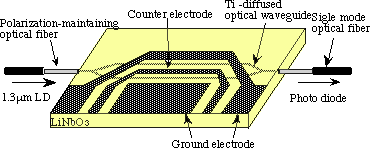
Fig. 1. Schematic of a traveling-wave type optical modulator with Ti:LiNbO3.
where v( 0, t ) is the modulation voltage at the input end x = 0, w=2pf
is the angular frequency, a is the attenuation
constant, b is the phase constant, Vp
is the half-wave voltage, l is the light wavelength,
s is the gap spacing, g33 is the electrooptic
coefficient, G is the overlap integral between
optical and microwave fields, N0 is the refractive index of lightwave,
L is the coupling length, q is the difference
of the electrical length between optical and signal waves, c is the light
velocity in free space, and Nm=c/(w/b) is the
effective refractive index of the signal wave.
In this case the intensity of the optical power at the output end
of the Mach-Zehnder optical modulator is given by
 (8)
(8)
where I0 is the maximum output power in the absence of modulation voltage,
i.e., Df,=0.
The variable F(w) given by Eq. (6) is proportional to the amplitude
of the optical phase difference, which is referred to as the normalized
modulation depth. This is an important variable which determines the bandwidth
of the modulator through the frequency characteristics of q
and a.
In the case of velocity matching between the optical wave
and the signal wave, i.e., No=Nm, Eq.(6) leads to the expression for the
modulation depth as
 (9)
(9)
In this case, the frequency dependence of F(w) originates from
that of a(f). From Eq.(9) we can define the optical 3 dB bandwidth Df
by the frequency which gives F(w)= 1/2. This
gives the relation
 (10)
(10)
Taking into account that the attenuation constant consists of conductor
loss and dielectric loss, and that the conductor loss is proportional to
the surface resistance, we assume the frequency dependence of the attenuation
constant to be given as
 (11)
(11)
 (12)
(12)
where an and as represent the attenuation constant of the normal-conductor
and the superconductor, respectively, acn0 and
acs0 are proportionality constants for conductor
loss and ad0 is the proportionality constant
for dielectric loss. Equations (10), (11) and (12) give the expressions
for the bandwidths as
 (13)
(13)
 (14)
(14)
where Dfn and Dfs
are the bandwidth for the normal-conductor and the superconductor, respectively.
In Fig.2 we show the cross-sectional view of the optical modulator
with coplanar waveguide and a shielding plane. It is shown that the conditions
for velocity matching and impedance matching are satisfied for w1=8[mm],
s=15[mm], d=1.8[mm], h1=h2=0.5[mm], h3=5.5[mm].
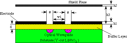
Fig. 2. Coplanar waveguide with a shielding plane.
In Fig.3 we show the threshold voltage calculated from (5) as a function
of coupling length L. In the calculation we used the values for the parameters:
l=1.55[mm], N0=2.15, g33=30.8×10⁻¹²[m/V],
G=0.867. We see that the threshold voltage,
i.e., modulation power, is decreased as L increases.
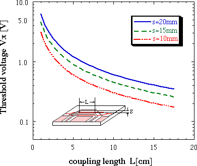
Fig. 3. Calculated threshold voltage Vp as a
function of coupling length L.
In Fig.4 we show the optical 3 dB bandwith as function of coupling
length L calculated from Eq.(13) and (14). In the calculation we used
the values for the attenuation constants: acs0=1.63×10⁻⁵[dB/cm・GHz2]
for Nb, acs0=2.16×10⁻⁴[dB/cm・GHz2] for YBCO,
acn0=0.43[dB/cm・GHz1/2] for Au given in [2],ad0=7.4×10⁻³[dB/cm・GHz]
corresponding to the loss tangent of LN as tand=0.005.The
attenuation constants for superconductors are estimated by numerical calculations
described in [13] using the complex conductivity for the superconductors
s=s1-js2,
where s1 is the conductivity due to normal-conducting
current and s2=1/wm0lL2
(lL:magnetic penetration depth) is the effective
conductivity resulted from superconducting current. In the present simulation
we used the following experimental values: s1=4.01×10⁶
[S/m], lL=0.2[mm] for YBCO, and s2=2.57×10⁷
[S/m], lL=0.05[mm] for Nb.
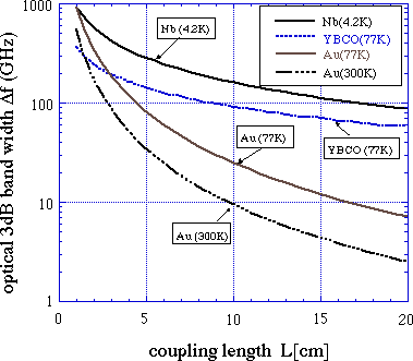
Fig. 4. Calculated optical 3dB bandwidth Df
as a function of coupling length L.
In Fig.5 we show the figure of merit of the modulator,i.e., Df/Vp
as a function of the coupling length. It is shown that for superconductors
the figure of merit increases as the coupling length increases.
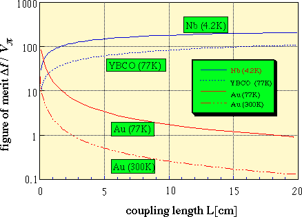
Fig. 5. Figure of merit Df/Vp
as a function of coupling length L.
In Fig.6 we show the waveforms of a rectangular pulse with the width
of 20[ps] traveling in various conductors which was calculated from (1)-(3),
(11) and (12). It is shown that the waveform decays greatly as the attenuation
constant increases. As a result, the modulation depth decreases when the
voltage pulse decays.
![Fig. 6. Waveforms of a pulse traveling in various electrodes (at L=0,5,10,15,20[cm]).](fig6.gif)
Fig. 6. Waveforms of a pulse traveling in various electrodes (at L=0,5,10,15,20[cm]).
In Fig.7, we show the waveforms of the optical output waveforms
calculated from (2)-(7) in the case of velocity matching for various conductors.
It is shown that the optical output decreases as the attenuation increases.
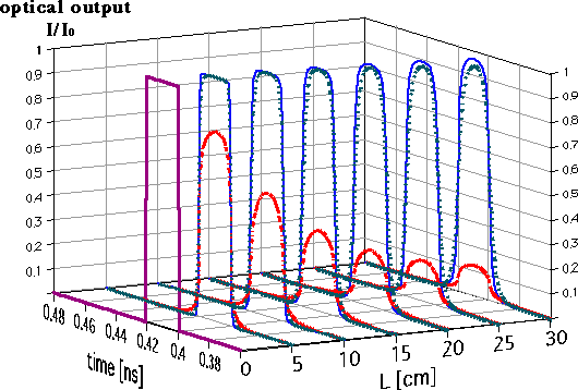
Fig. 7. Optical output waveforms in various electrodes.
back next
reference
top