III. EXPERIMENT
The optical modulator used in the present experiment was the traveling-wave
type Mach-Zehnder optical modulator with a shielding plane as shown in
Fig.8. Dimensions of the modulator is described in detail in [8]. We used
y-cut LiNbO3 substrate whose edges were mirror polished, and single mode
optical waveguides were formed by Ti diffusion into the surface of the
substrate. The transmission line for the signal wave and the shielding
plane were made of NbN. The coupling length L was 20[mm]. The fabrication
process of the shielding plane is shown in Fig.9. We made the shielding
plane with the various heights from 3[mm] to 7[mm] for velocity matching.
In the experiment we used a semiconductor laser with the wavelength
of l=1.3[mm]. In order to guide laser light
into the optical waveguide in LiNbO3 substrate we used a polarization maintaining
fiber at the input end and excided a TE mode in the optical waveguide.
We attached optical fibers to the mirror polished edge of the substrate.
The connection betweeen optical fibers and LiNbO3 substrate was made by
an adhesive which is hardened by illuminating ultra-violet light through
the use of minute glass tubes.
For measuring microwave modulation characteristics in the frequency
range between dc and 26.5[GHz], we adopted the envelope detection method
[11], [12], where the microwave response of the modulator can be estimated
by the time averaged response of the power meter even in the case when
the cutoff frequency of the power meter is much lower than the microwave
frequency.
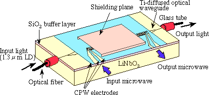
Fig. 8. Schematic of a traveling-wave-type optical modulator with a shielding
plane.
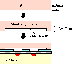
Fig. 9. Fabrication process of a shielding plane.
In Fig.10 we show the frequency dependence of the modulation depth with
and without shielding plane.The observed data were estimated by the procedure
given in [8] using the experimental values for basic parameters. The
solid lines in Fig.10 represents the theoretical curve which was calculated
from Eq.(6) using the attenuation constant a estimated from experimental
data. A good agreement between theory and experiment is obtained.
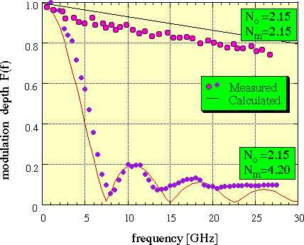
Fig. 10. Measured frequency dependence of modulation depth and calculated
values.
In the absence of a shielding plane, the quasi-periodic structure
originated from the velocity mismatch between the optical wave and the
signal wave, as was predicted from Eq.(6), was clearly seen. This sort
of periodic structure reflects the low-loss nature of the superconducting
electrode. In the case of velocity matching with a shielding plane, the
bandwidth is shown to be dramatically enhanced as predicted by theory.
The good agreement between theory and experiment also demonstrates the
validity of both the theoretical model of Eq.(4) and the present experimental
method. From this experiment we see that the LiNbO3 optical modulator with
a superconducting electrode can be operated as expected from theory.
back
next
reference
top